PTP IEEE 1588 is the time synchronisation standard that makes process bus work — and the one that, when configured incorrectly, produces fault record timestamps that do not align across IEDs. In a substation where sequence-of-events analysis depends on sub-millisecond timing accuracy, the difference between ±1 µs (what PTP delivers) and ±1 ms (what IRIG-B typically delivers over coax) is the difference between useful forensics and ambiguous ones.
Why PTP IEEE 1588 Accuracy Matters in a Substation
IEC 61850-9-2 (Sampled Values for process bus) requires time synchronisation accuracy of ±1 µs at the merging unit. This is not achievable with IRIG-B. It is not achievable with SNTP. It requires PTP — specifically the IEEE 1588-2019 Power Profile (also known as IEC 61850-9-3), which defines the PTP profile optimised for power system applications: two-step clock, peer-to-peer delay mechanism, and specific VLAN and priority requirements.
Even for station bus applications where Sampled Values are not in use, IEC 61850 recommends ±1 ms accuracy for event timestamping. IRIG-B on dedicated coax can meet this. PTP over Ethernet meets it with headroom to spare — which is why most new deployments specify PTP regardless of whether process bus is in scope.
The PTP Hierarchy: Grandmaster, Boundary Clock, Slave Clock
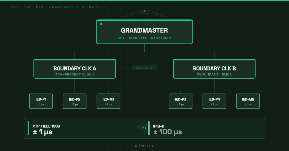
PTP operates in a master-slave hierarchy established by the Best Master Clock Algorithm (BMCA):
- Grandmaster clock: The primary time source — typically a GPS-disciplined clock with a PTP grandmaster module. It originates the PTP time and distributes it to the network.
- Boundary clock: A managed Ethernet switch with IEEE 1588 boundary clock capability. It terminates the PTP session on each port and re-originates it, compensating for switch queuing latency. This is why ordinary managed switches cannot carry PTP accurately over multiple hops — the queuing delay is not compensated and accumulates.
- Slave (ordinary) clock: The IED or merging unit. It receives PTP, synchronises its internal clock, and timestamps events accordingly.
For a typical station LAN, the architecture is: GPS grandmaster → boundary clock switch (per voltage level or per bay cluster) → IED slave clocks. This keeps the PTP hop count low and the accuracy budget achievable.
Grandmaster Redundancy — and What Happens When It Fails
A single GPS grandmaster is a single point of failure for the entire station’s time synchronisation. Most substation designs specify two grandmasters with automatic failover via BMCA. The BMCA selects the grandmaster based on clock quality parameters — GPS-disciplined clocks advertise high accuracy; a holdover clock (running on internal oscillator after GPS loss) degrades its clock quality and loses the BMCA election to a healthy GPS source.
What actually breaks when GPS fails and holdover kicks in:
- IRIG-B: Continues distributing the holdover time with no indication of degraded accuracy to the receiving IED. The IED timestamps events against a clock that is drifting. The drift rate depends on the oscillator quality — typically ±1 µs/s for a good TCXO, worse for a basic oscillator.
- PTP with BMCA: The degraded grandmaster advertises reduced clock quality. If a second healthy grandmaster is available, BMCA switches to it automatically. If not, IEDs continue with the holdover time but the degraded quality is visible in PTP management tools.
This is one reason why PTP provides better operational visibility than IRIG-B for a redundant time sync architecture.
IRIG-B Migration: The Decision Points
For substations that were commissioned with IRIG-B and are now being upgraded for IEC 61850 or process bus:
The migration decision depends on whether the IEDs being retained support PTP natively (most IEDs manufactured after 2015 do), whether the managed switches in the station LAN support boundary clock (many don’t — they need replacement or augmentation), and whether the GPS clock hardware has a PTP grandmaster module or only IRIG-B outputs.
A phased approach — replace the GPS clock first, add PTP grandmaster output, verify IED PTP accuracy, then remove IRIG-B — is more predictable than a simultaneous cutover.
Internal links: For process bus architecture where ±1µs is mandatory, see [Station Bus vs. Process Bus]. For the network design that carries PTP traffic, see [Substation Network Design for IEC 61850].
Signarid’s training covers PTP configuration, boundary clock setup, grandmaster redundancy testing, and IRIG-B migration planning — built on commissioning experience across GCC and India substations. Enquire about a training programme.